In industrial power transmission systems, a properly installed taper lock pulley should not slip. The taper lock mechanism is specifically designed to create a high-friction, interference-based grip between the shaft and the bush.
If slipping occurs, it indicates a mechanical, installation, or design-related issue that must be diagnosed systematically.
This guide is written specifically for maintenance engineers, plant engineers, and mechanical supervisors who need a technical and practical troubleshooting approach.
Understanding How a Taper Lock System Works
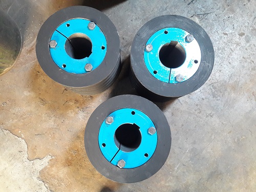
A taper lock assembly consists of:
- A pulley with tapered bore
- A matching taper lock bush
- Mounting screws
- Shaft (with or without key)
When bolts are tightened, the bush is pulled into the pulley’s tapered bore. This creates:
- Radial compression on the shaft
- Uniform pressure distribution
- High frictional locking force
The torque transmission capacity depends on:
- Shaft diameter
- Contact pressure
- Friction coefficient
- Correct tightening torque
- Surface condition
If any of these parameters are compromised, slipping may occur.
Step-by-Step Engineering Diagnosis
1. Confirm Whether It Is Shaft Slippage or Belt Slippage
Before dismantling, verify the actual issue.
Indicators of Shaft Slippage
- Pulley position shifts axially
- Key shows polishing marks
- Shaft surface shows rotational scoring
- Bush bore has heat discoloration
Indicators of Belt Slippage
- Squealing sound at startup
- Belt glazing
- Black rubber dust near pulley
- Speed drop under load
Misdiagnosis is common. Always verify first.
2. Installation Torque Verification
Improper bolt tightening is the most frequent root cause.
The clamping force generated by the bush depends directly on bolt preload. Under-tightened bolts reduce radial pressure, lowering torque capacity.
Check:
- Was a calibrated torque wrench used?
- Were bolts tightened in a progressive cross-sequence?
- Were bolts re-tightened after initial run-in?
Recommendation:
Follow manufacturer torque charts strictly. Recheck torque after 30–60 minutes of initial operation.
3. Shaft Surface Condition Analysis
The taper lock system relies on friction. Surface condition is critical.
Problematic Conditions:
- Oil or grease contamination
- Rust pitting
- Polished (mirror-finish) shaft
- Undersized shaft diameter
Friction coefficient reduces drastically in the presence of lubricant. Even a light oil film can reduce holding torque significantly.
Corrective Action:
- Clean with solvent
- Lightly roughen highly polished shafts
- Measure shaft diameter using micrometer
- Maintain recommended tolerance (typically h8 or equivalent)
4. Bush Selection and Load Calculation
Slippage may indicate undersized bush selection.
Verify transmitted torque using:
T = (9550 × Power in kW) / RPM
Compare calculated torque with bush rated torque capacity.
If transmitted torque exceeds rated capacity:
- Upgrade bush size
- Increase pulley diameter
- Use multi-groove system
- Reduce shock load
Heavy-duty applications require higher safety factors (1.5 to 2.5).
5. Shock Load and Cyclic Loading Effects
Applications such as crushers, hammer mills, or heavy conveyors generate:
- High starting torque
- Impact loads
- Torsional vibration
Repeated micro-movement between bush and shaft can gradually reduce grip.
Engineering Solution:
- Increase service factor
- Use larger bush series
- Consider key-assisted design
- Apply dynamic balancing
6. Key and Keyway Interaction (If Used)
Although taper systems can transmit torque without a key, many applications still use one.
Potential Problems:
- Oversized key
- Loose key fit
- Worn keyway
- Key bottoming out
A key that prevents full bush contraction reduces frictional grip.
Recommendation:
Ensure key does not interfere with full radial compression of bush.
7. Thermal Expansion Effects
In high-temperature environments:
- Shaft expands
- Bush expands
- Friction conditions change
Repeated heating and cooling cycles may reduce bolt preload.
Preventive Practice:
- Use correct tightening torque
- Re-check after thermal cycling
- Avoid operating beyond rated temperature limits
Engineering Checklist for Preventing Slippage
Before commissioning:
- Verify shaft tolerance
- Clean shaft and bore thoroughly
- Install bush dry (no lubrication)
- Tighten bolts progressively
- Use calibrated torque wrench
- Align pulley accurately
- Re-torque after initial operation
During operation:
- Monitor vibration levels
- Inspect for axial movement
- Check belt tension periodically
- Look for heat marks
Root Cause Summary
| Cause | Engineering Impact | Recommended Action |
|---|---|---|
| Low tightening torque | Reduced radial pressure | Re-torque bolts |
| Contaminated shaft | Reduced friction | Clean and reinstall |
| Undersized bush | Insufficient torque capacity | Upgrade bush |
| Shock loading | Micro movement | Increase service factor |
| Worn shaft | Reduced grip | Repair or sleeve shaft |
| Incorrect key fit | Prevents full contraction | Correct key size |
When Should You Replace Instead of Reinstall?
Replace the bush or pulley if:
- Bore shows scoring or fretting
- Taper surfaces are damaged
- Bolt threads are stretched
- Repeated slippage occurs after correct installation
Repeated slipping permanently reduces friction performance.
Final Engineering Insight
A taper lock pulley does not slip without reason. It is a mechanically sound locking system when correctly sized, properly installed, used within rated torque limits, and maintained periodically.
Most failures are procedural rather than product-related. Careful torque calculation, proper shaft tolerance, and correct installation practice eliminate slipping issues permanently.
For professional technical guidance and application-specific recommendations, contact Shree Ganesh Enterprise.